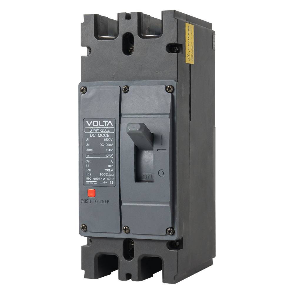
FUNCTION
The STWDIM5D partial series DC special circuit breaker (hereinafter referred to as the circuit breaker) is used in DC power grid circuits with a rated voltage of Dc250v, Dc1500v, and a rated working current of 63A ^ 800A. This circuit breaker has over load long delay and short-circuit instantaneous protection functions, which are used to distribute electricity and protect the circuit and power equipment from overload, short circuit and other fault hazards.
COMPLIANT WITH STANDARDS
GB/T14048.1 “Low voltage switchgear and control equipment – Part 1: General principles”
GB/T14048.2 “Low voltage switchgear and control equipment – Part 2: Circuit breakers”
NORMAL WORKING AND INSTALLATION CONDITIONS
The altitude of the installation site shall not exceed 2000m.
Allow the ambient temperature to be no higher than+70 C and no lower than -45 C; (For use with reduced capacity exceeding+40 C,
specific details must be negotiated with the manufacturer).
Atmospheric conditions: such as 90% at 20 *C C, and considering the condensation that occurs on the surface of the product due to
temperature changes, when the surrounding temperature is 40 ℃.
The relative humidity of the atmosphere shall not exceed 50%, and higher relative humidity is allowed a tower temperatures.
Pollution level is level 3.
The installation category is III.
Installation magnetic field: The magnetic field at the installation position shall not exceed 5 times the geomagnetic field in any direction.
In a medium without explosion risk, and there are no gases or conductive dust in the medium that are sufficient to corrode metals and damage insulation.
In areas without wind and snow erosion.
Installation conditions: Horizontal and vertical installation can be carried out, and there should be no significant impact or vibration at the installation site. It should not be installed in flammable and explosive places.
The circuit breaker has isolation function, with the symbol.